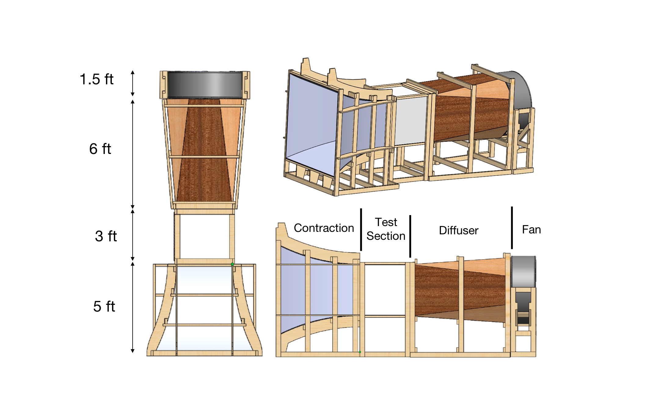
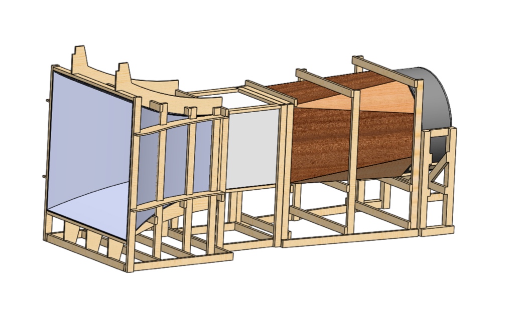
Student aerospace researchers at the University of Oklahoma had a problem. The students needed a quality wind tunnel to test full-scale UAV propeller designs and to serve as a testing ground for model airfoil designs. The University owned various wind tunnels, but each tunnel was an expensive, high-precision instrument that required difficult-to-obtain departmental permission and didn’t permit simple modifications for research purposes. In addition, none of the viable options had a large enough test-section to accommodate the full scale (~18 inch diameter) UAV propellers students had designed. Our professor started a group with $5000 seed funding to build an appropriate wind tunnel for these student research projects.
To build the desired low-cost and versatile wind tunnel, we started by defining the parameters and constraints of our build. We established the test section size, defined our desired flow velocity in the test section, and used previous articles to examine the diffuser and contraction-angle we would need to help prevent flow delamination and ensure flow uniformity in the test section. We developed simple computer-aided design (CAD) models of various closed and open-loop designs in Solidworks, then used Solidworks flow simulation and other Computational Fluid Dynamics (CFD) tools to examine the predicted flow uniformity in the test section. We selected an open-loop design based on the results of our CFD analyses, then decided on a building material and reinforced our model by adding supporting struts and beams to the design. We used many wood fabrications tools made available through the Innovation Hub at OU, including a Computer Numerical Control (CNC) machine to cut the more complex shapes out of plywood. We employed a modular design to assemble and create the structure, building in sections and transporting the completed sections to the Westheimer airport in Norman, the final location for the tunnel. Once the tunnel was completed and assembled, we used a hot-wire anemometer to gain point-wise flow velocity measurements in the test section as part of our uniformity study. Further details about the building process and the uniformity study are included in the attached conference paper.
Through this project, I learned how to plan a project by considering both constraints and requirements and developing a project plan to satisfy features in both essential categories. I gained project experience with applying design and analysis tools (CAD and CFD, respectively), and learned to appreciate the value that these tools can contribute to informing design. This project was an excellent chance to employ mechanical engineering design skills and to help build a tool for other to use and appreciate.

